Use case diagram is used to capture the dynamic nature of a system.
It consists of use cases, actors and their relationships. Use case diagram is used at a high level design to capture the requirements of a system.
To model a system, the most important aspect is to capture the dynamic behavior.
The dynamic behavior means the behavior of the system when it is running /operating.there should be some internal or external factors for making the interaction.
These internal and external agents are known as actors. So use case diagrams consist of actors, use cases and their relationships. The diagram is used to model the system/subsystem of an application. A single use case diagram captures a particular functionality of a system.
Use case diagrams are used to gather the requirements of a system including internal and external influences. These requirements are mostly design requirements. So when a system is analyzed to gather its functionalities use cases are prepared and actors are identified.
The purposes of use case diagrams can be as follows.
- Used to gather requirements of a system.
- Used to get an outside view of a system.
- Identify external and internal factors influencing the system.
- Show the interacting among the requirements are actors.
BUILDING BLOCKS OF USE CASE DIAGRAM
The building blocks of UML can be defined as:
- Things
- Relationships
- Diagrams
Things: Things are the most important building blocks of UML. Things can be:
- Structural
- Behavioral
- Grouping
- Annotational
Structural things: The Structural things define the static part of the model. They represent physical and conceptual elements. Following are the brief descriptions of the structural things.
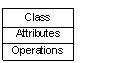
Class: Class represents set of objects having similar responsibilities.
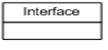
Interface: Interface defines a set of operations which specify the responsibility of a class.
Collaboration: Collaboration defines interaction between elements.

