ACTION STATE\ ACTIVITY STATE
As elements communicate with one another within a society of objects, each element has the responsibility of appropriately reacting to the communications it receives. An action state represents processing as an element fulfills a responsibility.
There are various types of action states, including simple, initial, and final action states.
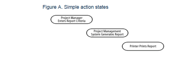
Simple Action States
A simple action state represents processing. For example, the project management system may have the following simple action states:
Project Manager Enters Report Criteria : Indicates that the project manager enters report criteria
Project Management System Generates Report : Indicates that the project management system generates a report
Printer Prints Report : Indicates that the printer prints the report
In the UML, an action state is shown as a shape with a straight top and bottom and convex arcs on the two sides, and is labeled with the name of an operation or a description of the processing.
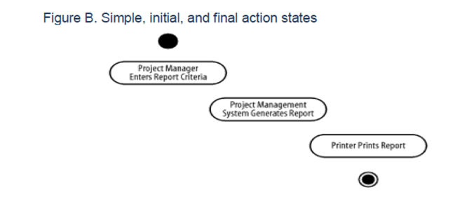
Initial and Final Action States
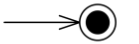
An initial action state indicates the first action state on an activity diagram. In the UML, an initial action state is shown using a small solid filled circle. A final action state indicates the last action state on an activity diagram. In the UML, a final action state is shown using a circle surrounding a small solid filled circle (a bull’s eye).
An activity diagram may have only one initial action state, but may have any number of final action states.
OBJECT NODE
An object node is an activity node that is part of defining object flow in an activity. It indicates that an instance of a particular Classifier, possibly in a particular state, may be available at a particular point in the activity. Object nodes can be used in a variety of ways, depending on where objects are flowing from and to. Object nodes are notated as rectangles. A name labeling the node is placed inside the symbol, where the name indicates the type of the object node, or the name and type of the node in the format “name:type.”

CONTROL NODE
Control node is an activity node used to coordinate the flows between other nodes. It includes:
Initial Node Initial node is a control node at which flow starts when the activity is invoked. A control token is placed at the initial node when the activity starts, but not in initial nodes in structured nodes contained by the activity. Tokens in an initial node are offered to all outgoing edges. For convenience, initial nodes are an exception to the rule that control nodes cannot hold tokens if they are blocked from moving downstream, for example, by guards. Activity may have more than one initial node. In this case, invoking the activity starts multiple flows, one at each initial node. Note that flows can also start at other nodes, so initial nodes are not required for an activity to start execution. Initial nodes are shown as a small solid circle.

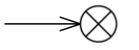
Flow Final Node Flow final node is a control final node that terminates a flow. It destroys all tokens that arrive at it but has no effect on other flows in the activity. Flow final was introduced in UML 2.0. The notation for flow final node is small circle with X inside.
Activity Final Node
Activity final node is a control final node that stops all flows in an activity. Activity final was introduced in UML 2.0. An activity may have more than one activity final node. The first one reached stops all flows in the activity. A token reaching an activity final node terminates the activity. In particular, it stops all executing actions in the activity, and destroys all tokens in object nodes, except in the output activity parameter nodes. Terminating the execution of synchronous invocation actions also terminates whatever behaviors they are waiting on for return. Any behaviors invoked asynchronously by the activity are not affected. If it is not desired to abort all flows in the activity, use flow final instead. Activity final nodes are shown as a solid circle with a hollow circle inside. It can be thought of as a goal notated as “bull‘s eye,” or target.
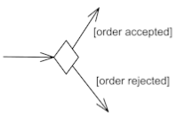
Decision Node
Decision node is a control node that accepts tokens on one or two incoming edges and selects one outgoing edge from one or more outgoing flows. Decision nodes were introduced in UML to support conditionals in activities. The edges coming into and out of a decision node, other than the decision input flow (if any), must be either all object flows or all control flows. Each token arriving at a decision node can traverse only one outgoing edge. Tokens are not duplicated. Each token offered by the incoming edge is offered to the outgoing edges. Which of the edges is actually traversed depends on the evaluation of the guards on the outgoing edges. The order in which guards are evaluated is not defined, i.e. we should not rely on any visual or text description order. The notation for a decision node is a diamond-shaped symbol.