A sequence diagram shows elements as they interact over time, showing an interaction or interaction instance.
Sequence diagrams are organized along two axes: the horizontal axis shows the elements that are involved in the interaction, and the vertical axis represents time proceeding down the page. The elements on the horizontal axis may appear in any order.
Elements of a sequence diagram
Sequence diagrams are made up of a number of elements, including
- class roles.
- specific objects.
- lifelines.
- activations.
Class roles
In a sequence diagram, a class role is shown using the notation for a class as defined in previously, but the class name is preceded by a forward slash followed by the name of the role that objects must conform to in order to participate within the role, followed by a colon. Other classes may also be shown as necessary, using the notation for classes, Class roles and other classes are used for specification-level collaborations communicated using sequence diagrams.
Specific objects
In a sequence diagram, a specific object of a class conforming to a class role is shown using the notation for objects, but the object name is followed by a forward slash followed by the name of the role followed by a colon followed by the class name, all fully underlined. Other objects may also be shown as necessary using the notation for objects.
Specific objects conforming to class roles and other objects are used for instance-level collaborations communicated using sequence diagrams.
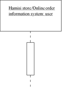
Lifelines
A lifeline, shown as a vertical dashed line from an element, represents the existence of the element over time.
Activations
An optional activation, shown as a tall, thin rectangle on a lifeline, represents the period during which an element is performing an operation. The top of the rectangle is aligned with the initiation time, and the bottom is aligned with the completion time.
COMMUNICATION
In a sequence diagram, a communication, message, or stimulus is shown as a horizontal solid arrow from the lifeline or activation of a sender to the lifeline or activation of a receiver.
In the UML, communication is described using the following UML syntax:
[guard] *[iteration] sequence_number : return_variable := operation_name (argument_list)
in which:
guard: Is optional and indicates a condition that must be satisfied for the communication to be sent or occur. The square brackets are removed when no guard is specified.
iteration Is optional and indicates the number of times the communication is sent or occurs. The asterisk and square brackets are removed when no iteration is specified.
sequence_number Is an optional integer that indicates the order of the communication. The succeeding colon is removed when no sequence number is specified. Because the vertical axis represents time proceeding down the page on a sequence diagram, a sequence number is optional.
return_variable Is optional and indicates a name for the value returned by the operation. If you choose not to show a return variable, or the operation does not return a value, you should also omit the succeeding colon and equal sign.
operation_name Is the name of the operation to be invoked.
argument_list Is optional and is a comma-separated list that indicates the arguments passed to the operation. Each parameter may be an explicit value or a return variable from a preceding communication. If an operation does not require any arguments, the parentheses are left empty.
Example
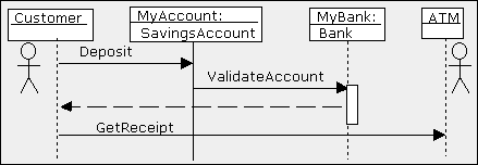
The Sequence diagram allows the person reading the documentation to follow the flow of messages from each object. The vertical lines with the boxes on top represent instances of the classes (or objects).
The label to the left of the colon is the instance and the label to the right of the colon is the class. The horizontal arrows are the messages passed between the instances and are read from top to bottom.
- a customer (user) depositing money into MyAccount which is an instance of Class SavingsAccount.
- Then MyAccount object Validates the account by asking the Bank object, MyBank to ValidateAccount.
- Finally, the Customer Asks the ATM object for a Receipt by calling the ATM‘s operation GetReceipt.
TYPES OF MESSAGES
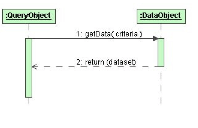
Synchronous Messages
- assumes that a return is needed
- sender waits for the return before proceeding with any other activity
- represented as a full arrow head
- return messages are dashed arrows
Asynchronous Messages
- does not wait for a return message
- sender only responsible for getting the message to the receiver
- usually modeled using a solid line and a half arrowhead to distinguish it from the full arrowhead of the synchronous message

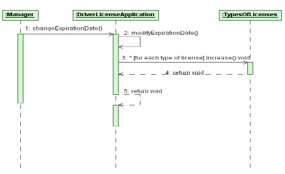
Self-Reference Message
A self-reference message is a message where the sender and receiver are one and the same object.
1. In a self-reference message the object refers to itself when it makes the call
2. message 2 is only the invocation of some procedure that should be executed
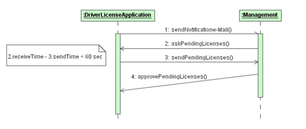
Timed Messages
- messages may have user-defined time attributes, such as sentTime or receivedTime
- user-defined time attributes must be associated with message numbers
- instantaneous messages are modeled with horizontal arrows
- messages requiring a significant amount of time, it is possible to slant the arrow from the tail down to the head Object Creation and Destruction